I have been doing some experiments to get load cells working with Arduino.
This is a collection of my experiences. Something about:
- What is a load cell
- How did I wire it up to an Arduino board
- What crazy application did I use it for?
- Light was controlled by using diode boxes and Sonny Windstrupsgreat code
- Music was controlled by using Pure Data to read the Arduino board and generate a midi-controller to use in Ableton Live.
- Dancing: Allison Lorenzen and others. Mounting: Thomas Fabrik. Rigging: Karl Gillick. Interactive music: Bo Boye.
So.. What is a load cell anyway
A digital weight.
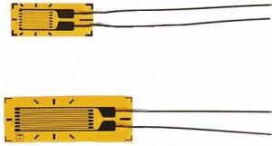
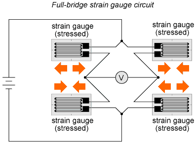
Usually a piece of steel containing one or more Strain Gauges arranged in a Wheatstone bridge.

How to get a load cell
The load cell I have been using is a commercial one. (SKANTRONICS FH SERIES – STAINLESS-STEEL Shear Beam Load Cell)
These are quite expensive if you are heading to buy one.
Break a digital weight
There is actually a load cell sitting inside any digital weight you can find. Paper weight, Bath weight.
Buy or find a cheap one, and take it apart. Then rehook the loadcell inside.
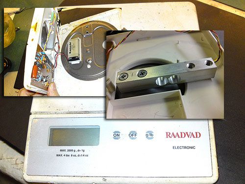
Its a little bar of steel with 4 wires coming out of it.
The 4 wires are pretty standard color coded.
Look here for a good reference:http://www.controlweigh.com/loadcell_colors.htm
You can play around with the gain to get the accuracy you want.
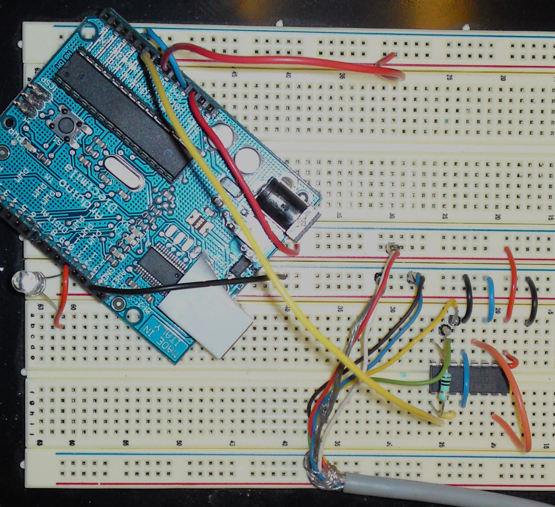
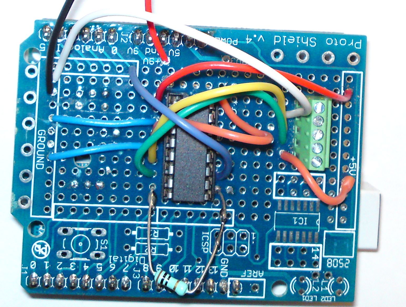
Connecting a load cell to an Arduino board
You need some sort of microvolt amplifier to read the minute change in volt over the bridge.
ina125P – An IC that does it all for you.
- Very simple to use.
- Cheap. Around 7 € at Farnell
- Usable for many different instrumentation amplifications
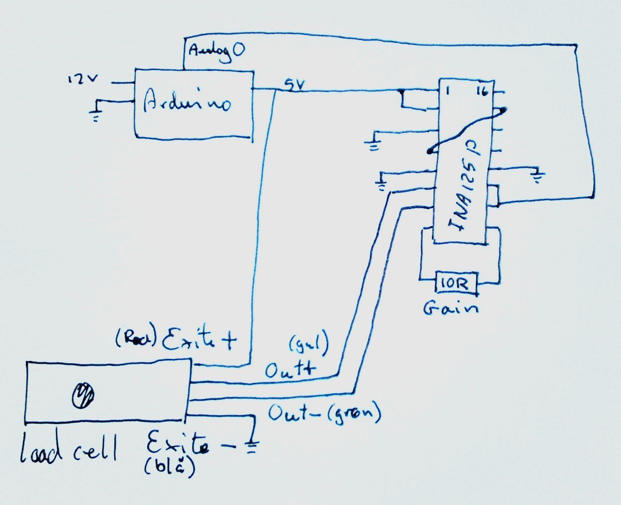
The resistor sets the gain. Look in the datasheet of the ina125p for details.

Simple arduino example
This is a simplified example of how to convert your load cell analog readings to kilo/load.
// Arduino as load cell amplifier
// by Christian Liljedahl
// christian.liljedahl.dk
// Load cells are linear. So once you have established two data pairs, you can interpolate the rest.
// Step 1: Upload this sketch to your arduino board
// You need two loads of well know weight. In this example A = 10 kg. B = 30 kg
// Put on load A
// read the analog value showing (this is analogvalA)
// put on load B
// read the analog value B
// Enter you own analog values here
float loadA = 10; // kg
int analogvalA = 200; // analog reading taken with load A on the load cell
float loadB = 30; // kg
int analogvalB = 600; // analog reading taken with load B on the load cell
// Upload the sketch again, and confirm, that the kilo-reading from the serial output now is correct, using your known loads
float analogValueAverage = 0;
// How often do we do readings?
long time = 0; //
int timeBetweenReadings = 200; // We want a reading every 200 ms;
void setup() {
Serial.begin(9600);
}
void loop() {
int analogValue = analogRead(0);
// running average - We smooth the readings a little bit
analogValueAverage = 0.99*analogValueAverage + 0.01*analogValue;
// Is it time to print?
if(millis() > time + timeBetweenReadings){
float load = analogToLoad(analogValueAverage);
Serial.print("analogValue: ");Serial.println(analogValueAverage);
Serial.print(" load: ");Serial.println(load,5);
time = millis();
}
}
float analogToLoad(float analogval){
// using a custom map-function, because the standard arduino map function only uses int
float load = mapfloat(analogval, analogvalA, analogvalB, loadA, loadB);
return load;
}
float mapfloat(float x, float in_min, float in_max, float out_min, float out_max)
{
return (x - in_min) * (out_max - out_min) / (in_max - in_min) + out_min;
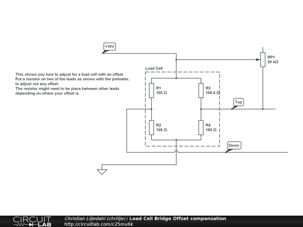
}DC offset
If you are having an offset in you load cell, you need to add a resistor to compensate. This circuit should show you how:
Other considerations
- I am using the 5V of the Arduino board as exitation to the load cell, not the 5v-ref on the chip
- Using a 1760 kg load cell I was able to sense 0.1 kg changes
- You may have to swap the voltage applied to the bridge to get a decent range on the analog signal
- Measure the output voltage (input to analog 0) while you change your load, and adjust the gain until you get a good sense
- Analog input at the arduino board is used. Play around with the aref – analogreference – to get a good sense.
- analogReference in my sketch was set to INTERNAL making it 1.1 V – Wich gave me a good range