
Using just a small dc-motor and a resistor to make a crude rotary encoder for the Arduino.
I came up with a very simple way to make rotary encoders. I needed a "turn the handle" interface for an installation. Usually, this can be solved with either a potmeter or a really fancy precision rotary encoder. But both have drawbacks. Potmeters need "end stops" to block overturning them.Fancy rotary encoders need high sampling rates, and take up several legs on the arduino each.
But: What spins and are good at it: A DC motor. Reversing it and using it as a generator, you suddenly have a simple way of knowing "Witch way are they turning the wheel, and how fast".
You need
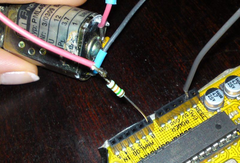
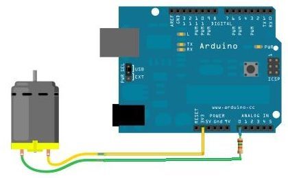
- A small DC motor (permanent magnet type)
- A resistor (10-20K)
- An Arduino Board
| Analog input value | ||
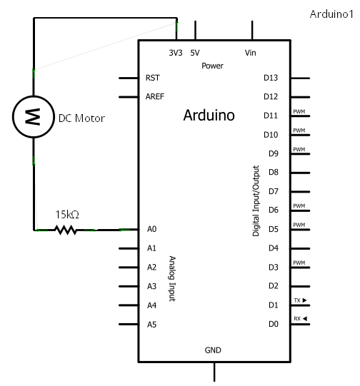
| No rotation | The 3.3 V "flow" right through the windings of the DC motor | 676 (1024/5*3.3) |
| Spin one way | The DC motor acts as a generator, making maybe + 1 V (depending on the speed of your rotation). This is "added" to the + 3.3 V = 4.3 V | 880 (> 676 : one way) |
| Spin other way | DC motor makes - 1 V. This gets "subtracted" from the +3.3V = 2.3 V |
471 (<676 : other way) |
Considerations
- ? Why not make 2.5 volt with a voltage divider and feed that to the DC motor, to get the zero-rotation to read 512 on the analog input?
- ! Because you get bonus points for solving a problem with as few extra parts as possible.. :-)
- ? Why the 15K resistor?
- ! If the DC motor is spun really fast, the "overpower" to the Arduino Board makes it shut down. The resistor prevent this.
The code
This is the code from the Color & Sound installation. It uses the DC motors as encoders, and outputs DMX to control lights.
#include
#include <DmxSimple.h>

/*
Christian Liljedahl, 2010. christian.liljedahl.dk christian@liljedahl.dk

Example of how to use 6 DC motors as rotary encoders for Arduino

This code returns a position on a circle (CirclePosition) from 0.0 to 1.0

If the DC motor is not rotating, the CirclePosition is not moving either
Once the DC motor is turned one way, CirclePosition starts moving up (or down). The speed depends on how fast the encoder (DC motor) is rotated.

Please note: CirclePosition is not the position of the axis of the DC motor. There is no way (to my knowledge) this setup can give you the position of the DC motor.
Only: Are we turning clockwise or counterclockwise
*/

// Arrays to keep readings
int AnalogInReading[6];
int AnalogZeroPoint[6];
double RotationSpeed[6];
double CirclePosition[6];

void setup() {
  // DMX stuff - This program controlls colors.
  DmxSimple.maxChannel(30);
  //Serial
  Serial.begin(9600);

  // Make a reading
  readAllAnalog();
  // Set zeropoints
  calibrate();
  // Set starting point for cirle
  initPositions();
}

long time = 0;

void loop() {
  // read the value from the sensor:
  readAllAnalog();
  calculateRotationSpeed();
  changeCirclePosition();

  //FictionalRotationValues();
  makeHueAndSendDmx();
}

void setDmxValues(byte rgb[], int startchannel){
  DmxSimple.write(startchannel, rgb[0]);
  startchannel++;
  DmxSimple.write(startchannel, rgb[1]);
  startchannel++;
  DmxSimple.write(startchannel, rgb[2]);
  startchannel++;
  DmxSimple.write(startchannel, 255);

}
void readAllAnalog(){
  for(int i=0;i<6;i++){
    AnalogInReading[i] = analogRead(i);
  }
}

void calibrate(){
  for(int i=0;i<6;i++){
    AnalogZeroPoint[i] = AnalogInReading[i];
  }
}

void initPositions(){
  for(int i=0;i<6;i++){
    CirclePosition[i] = 0.5;
  }
}

void calculateRotationSpeed(){
  for(int i=0;i<6;i++){
    RotationSpeed[i] = AnalogZeroPoint[i] - AnalogInReading[i];
  }
}

void changeCirclePosition(){
  for(int i=0;i<6;i++){
    // What way do we rotate
    double rotFactor = (RotationSpeed[i]*RotationSpeed[i]-400)/1000000;
    if(RotationSpeed[i] > 20){

      // How fast do we rotate
      CirclePosition[i] += rotFactor;
      // Wrap around
      if(CirclePosition[i] > 1.0) CirclePosition[i] = 0.0;
    }
    if(RotationSpeed[i] < -20){
      CirclePosition[i] += -rotFactor;
      // Wrap around
      if(CirclePosition[i] < 0.0) CirclePosition[i] = 1.0;
    }
  }
}

void makeHueAndSendDmx(){
  // Dmx start address of first fixture
  int channel = 1;

  for(int i=0;i<6;i++){
    byte colors[3];
    // We use the circlepositoin directly for Hue, since CirclePosition is 0.0-1.0
    double Hue = CirclePosition[i];
    // Make sure we don't get an overflow issue
    Hue = constrain(Hue, 0.0, 1.0);
    // Convert the CirclePosition-Hue to RDRB for the dmx
    HSL2RGB(colors, Hue, 1.0, 0.6);
    // Send the colors to the fixture
    setDmxValues(colors, channel);
    // Move to next fixture
    channel += 4;
  }
}


// Given H,S,L in range of 0-1
// Returns a Color (RGB struct) in range of 0-255
void HSL2RGB(byte rgb[], double h, double sl, double l)
{
  double v;
  double r,g,b;

  r = l;   // default to gray
  g = l;
  b = l;
  v = (l <= 0.5) ? (l * (1.0 + sl)) : (l + sl - l * sl);
  if (v > 0)
  {
    double m;
    double sv;
    int sextant;
    double fract, vsf, mid1, mid2;

    m = l + l - v;
    sv = (v - m ) / v;
    h *= 6.0;
    sextant = (int)h;
    fract = h - sextant;
    vsf = v * sv * fract;
    mid1 = m + vsf;
    mid2 = v - vsf;
    switch (sextant)
    {
    case 0:
      r = v;
      g = mid1;
      b = m;
      break;
    case 1:
      r = mid2;
      g = v;
      b = m;
      break;
    case 2:
      r = m;
      g = v;
      b = mid1;
      break;
    case 3:
      r = m;
      g = mid2;
      b = v;
      break;
    case 4:
      r = mid1;
      g = m;
      b = v;
      break;
    case 5:
      r = v;
      g = m;
      b = mid2;
      break;
    }
  }
  //ColorRGB rgb;

  rgb[0] = byte(r * 255.0f);
  rgb[1] = byte(g * 255.0f);
  rgb[2] = byte(b * 255.0f);

}


void dumpAnalogReadings(){
  for(int i=0;i<6;i++){
    Serial.println(AnalogInReading[i]);
  }
  Serial.println("---");
}

void FictionalRotationValues(){
  RotationSpeed[0] = 0;
  RotationSpeed[1] = 100;
  RotationSpeed[2] = 200;
  RotationSpeed[3] = 300;
  RotationSpeed[4] = 400;
  RotationSpeed[5] = 500;
}