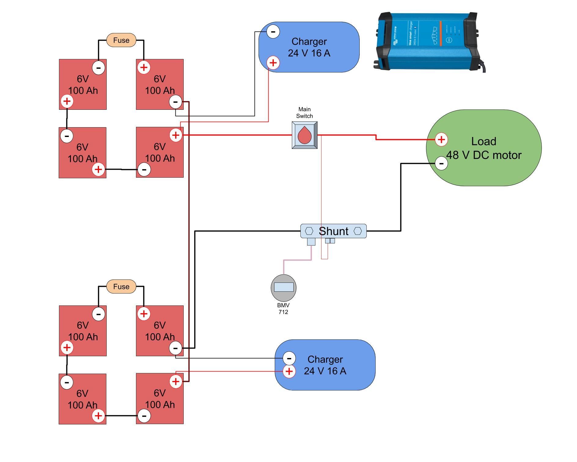
I wanted to measure the voltage of the lead batteries in my battery bank for my sailboat. I have 8 x 6V batteries, and I would love to be able to measure each battery individually.
Using resistors to divide the voltage down
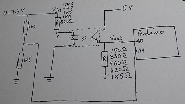
First setup used an array of resistors, dividing the battery voltage down to something useful to inject into an Arduino for measuring.
After posting this to Electric Boats and Electric Ships Michael Abrain suggested using LEDs and a phototransistor for measuring the voltage.
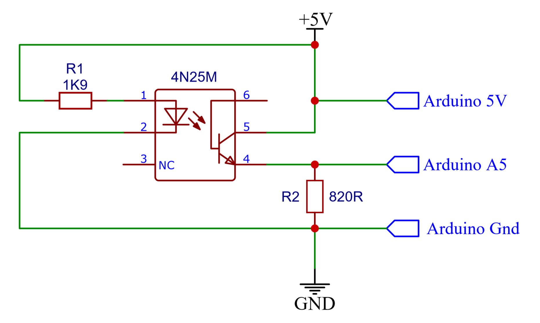
Using optocouplers
I have done a couple of experiments using a common optocoupler - 4N25 - as the combined LED and phototransistor. The datasheet suggests, that it behaves fairly linear in at least some of the current ranges passed through it.
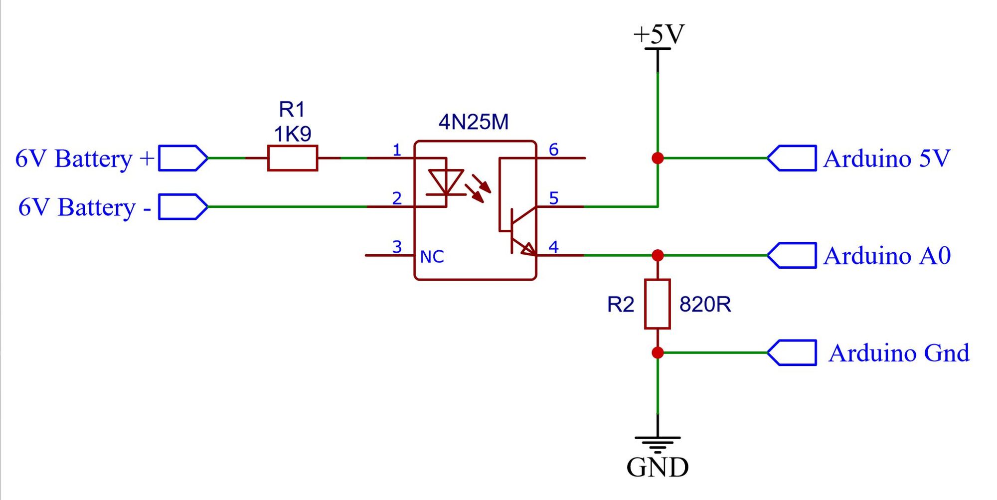
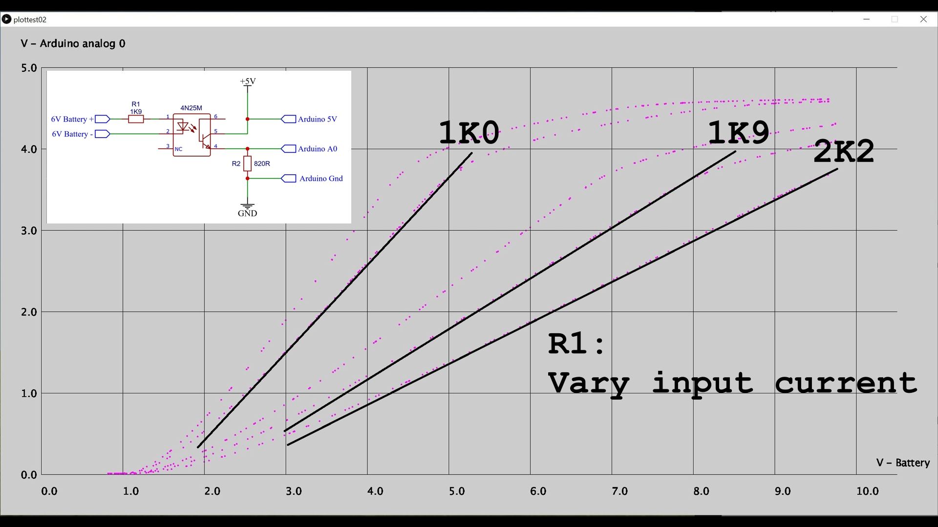
Playing with the input current (R1) and the output current (R2) it was possible to get fairly linear response in the voltage area I am iterested in.
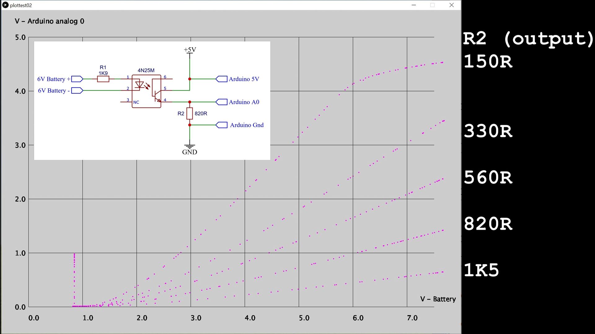
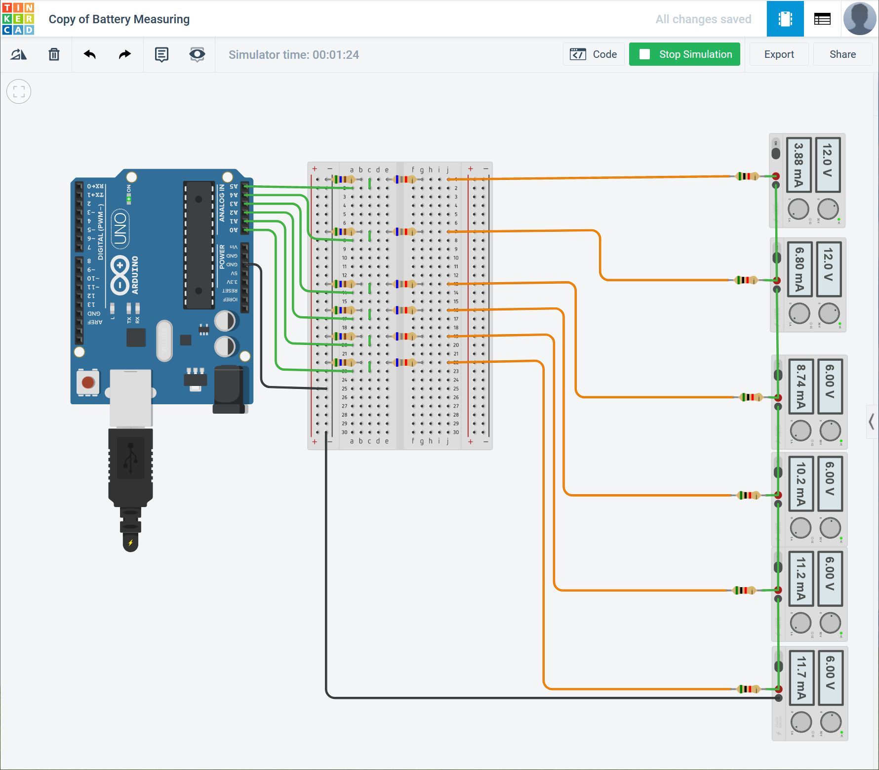
I am logging the voltage using a small sketch on the Arduino and a Processing sketch to graph it.
Here is the setup videoed on my messy desktop.
Accuracy of the two methods
Using the first method (resistor dividers) 0-1023 (10 bit) / 8 batteries = 127 pr battery
Using optocouplers we can use the full 0-1023 range giving much better accuracy
Temperature dependency
I did a little test heating the 4N25 to 100°C and comparing the measurements to that of 25°C and it looks like this gives about 5% difference in the voltage reading. Not much to be concerned about.

The optocoupler has some temperature dependency - If we want to compensate for this, we could connect one extra optocoupler to the Arduino like this:
All this to monitor the battery bank at our sail boat with an electric outboard engine.
Code to read the voltage (Arduino) and display it (Processing)